Steve's Triumph Spitfire 1600
The ongoing saaaaaaga

Exhaust:
I'll re-emphasize my earlier, very important point about mounting the engine assembly as close to the bonnet as possible (one inch works great) to provide more room below to fit the exhaust.
Header
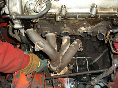
I was a little concerned about the Exhaust Task because of a few uncertainties including just procuring Mandrel Bent (MB) tubing and even more, if we would have room to get the welder between the collector pipes at the various locations where they get tight. Also the Miata header has been known to develop cracks and my collector did have the look of a few minor ones, so we put some quick beads of weld on those as well.
NOTE
In my research, probably the best web-site for header construction I found was
“Headers By “Ed” Inc.”. http://www.headersbyed.com/hc_buildbetter.htm
Miata Collector pipes are 1.5” and the rest of the exhaust is 2”, all very nice thickness steel. That matched well to my already modified system with 2” to the tailpipe.
Managed to get some Mandrel Bent (MB) Tubing from "Hot Rod Scott's" and "Performance Improvements", but the curve had a pretty large radius. Those kind, or better pieces are available on-line, especially in the States, but of course shipping, customs and taxes kill us Canadians, and I hadn't really thought ahead so we did what we could to get things going quickly.
In hindsight, of course for this application, the tighter the bend the better.
Routing
The original Miata Header goes back behind the Engine Mount and then between the sub-frame and Transmission. The Spitfire Frame tapers in much more quickly and does not provide room for that routing. Our solution from the get-go was to route it forward of the new Engine Mounts.
The geometry wasn't looking promising to get that collector, the main flange, and 2" pipe in that small space but we managed.
Our biggest considerations were to...
-
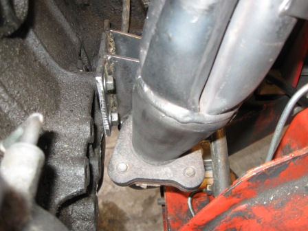
Position the intact Miata Collector, O2 Sensor, and Flange in the best location,
-
To get as smooth exhaust flow as we could manage, and finally,
-
An accessible Oxygen Sensor location with no interference from the Engine, Frame or Engine Mount.

Our solution was to leave intact as much of the header as possible. We cut each pipe an inch or so from the plate/flange, which meant pretty straight forward welding tube-to-tube and no concern about warping the flange. This also allowed us to manipulate the assembly in the area it needed to go for final installation with the engine and mounts already in place. We simply slid the Header forward to roughly have the number 2 and 3 pipes lined up with number 1 and 2 cylinders. This gave us good spacing from the Oil Pan, Frame Rail, and Engine Mount.
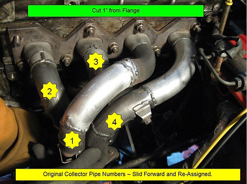
We needed numbers 3 and 4 to first go out horizontally before going to the collector (room to weld between pipes) so after horizontal it goes up then down into the collector. For the curved pieces of pipe we used some bends we cut out of the original, some from the mandrel bends, as well as notching out some bends to make them a bit tighter. Also made a few short straight sleeves to connect stuff, annnnd the O2 sensor has a great location!
As mentioned earlier the collector pipes are not equal lengths, although neither were the factory pipes.
The 1 HP will not be missed and tuning has not been an issue.
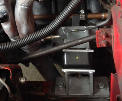
As a point of clarification, I had to add some wire to the O2 Sensor to have it reach its factory position near the coils, pretty easy, but wanted to mention it.
Just used wire from an old O2 Sensor and spliced it in with its protective sheathing, and of course, keeping intact the electrical connector..
Interesting Tid-Bit
Sometime after the majority of this build was complete my brother found something on-line that we found super-interesting. The guys at "Engine Masters " put this terrific video together. Very unbiased, and in a totally controlled environment. A very big thanks to them, most cool.
This shows how significantly deforming headers had next to no effect on performance. https://www.dailymotion.com/video/x3mt768
Aside: the link to that video seems to change periodically; if it doesn't work I find it using the search "Engine Masters bash exhaust header".
It was actually titled..."Exhaust Header Bash! Testing Power Loss From Dents - Engine Masters Ep. 4"
I am not for one second trying to say that changing collector pipe lengths or diameters will have the same negligible effect, but merely that sometimes we over-value some of the details.
Cutting ‘em
To cut the pipes I entertained purchasing a Metal Cutting Chop Saw (on sale at Princess Auto) but for under $10 I just bought a 10” metal cutting blade to fit into my mitre saw. Certainly not the best option, but with some care it worked awesome.
Supporting the System
The Miata had a structural support from the intermediate pipe to the engine block and we certainly think that is a good idea; not something we wanted to deal with right now, we wanted one that could easily be retrofitted after proof-of-concept panned out. It will definitely come later, likely attached to the header flange.

Intermediate Pipe
An intermediate pipe was put together mostly with scraps from both original systems and one new 2” MB J-Bend from "Performance Improvements". This is where we were fortunate that the engine and tranny ended up higher than initially planned. I'd say we had just the right amount of room here to fit the exhaust within the rails. Even with that it only allowed us to fit the shortest flex pipe I could find. Although the original Miata didn't have one; we felt it a good idea.
Butt-welding thin exhaust pipe (the MB one… factory Mazda stuff was very nice) is not fun and I anticipated some burn-through with my limited skill. It wasn't that bad, but I'd have preferred thicker walled pipe.
I was hoping to find some 2" Inside Diameter pipe to make some simple couplings as they would be easiest to weld, but didn't have any luck. I picked up a cheap pipe expander from "Princess Auto" and although knowing its shortcomings, modified the assembly to hopefully stretch some of our pipe to 2” ID. The Expander quickly broke as we kind of expected, so....
When ordering the flex pipe from my guys at “77 Auto Parts” I purposely got the one designated for assembly with clamps; this version comes with a few inches of 2" ID pipe at each end; we harvested a few couplings out of that extra material just leaving enough on the flex pipe to slide over the normal pipe and be welded together.


Those couplings proved very helpful, not just for welding, but even more-so for fitment and alignment before welding. They really helped to keep things intact when we had only 4 hands and limited space to test fit many little pieces of curved pipe. Quick Clamps certainly work, but nothing is as simple as couplings and a few spot welds.
I'm a huge fan of things that easily come apart for maintenance and I've never seen a clamped pipe that actually did that, so we continued with the use of flanges....sweet.
Tail Pipe and Muffler
Personally I've always hated the look of the ungainly and rather expensive low-hanging muffler on the stock Spitfire, so for considerably less money way back when I got the system done for the original 1500 motor, I had it improved by "Zoro Muffler" with their in-stock options.
They also put a flange on my previous PaceSetter header and of course on the new 2” pipe going all the way aft.
After getting the Intermediate Pipe sorted out, we massaged the Aft Pipe Flange location, cut and re-welded so it would line up with the new stuff, and then turned to securing the Aft Pipe to the car.
Hanging the thing in those tight quarters had me concerned as I wanted it close to the tub for ground clearance, but of course not rattling. Welding normal rod hooks would work, but I was concerned with them getting in the way if I later had to remove the prop shaft or such.
I came up with a twist-proof hanging system that bolted up to the small tub supports near the tranny output so no overhead welding to the frame. Used some bolts and on-hand Honda Prelude rubber hangers and bolted it up without welding the bracket to either the pipe or the tub. Probably more complex than required but it sure works well.

More details….
As mentioned, locally I found it difficult to track down some mandrel bent tubing.
"Hot Rod Scott’s" was the only one of 9 local shops that could get me this stuff (until I later found out that “Performance Improvements” and “Johnston Research & Performance” also can).
For the Collector Pipes, I bought (2x) 1.5” J-bends from Scott at $18 each, made by Dynamax.
Unfortunately they are 8” diameter bends (4” radius); I didn’t think tight enough for what I needed.
In the end we made it work and only needed one as we reused some of the pieces of the original header we had cut out.
Vibrant is a manufacturer in the US; I downloaded their catalogue and found some local dealers including “Johnston Research & Performance” in Mississauga.
Vibrant goes down to 3” radius.
Part number 12601 is CDN$45.95 each and would take one week to get.
“Performance Improvements” deals with both Vibrant and Hooker stuff and they gave me some amazing options.
For 1.5” steel MB J-Bends...
-
2” radius (4” diam) $28
-
2.5” radius (didn’t get a price)
-
3” radius (6” diam) $42
I already bought the other 1.5” pipe from Scott so too late for that, but they had on hand a 2” MB J-bend for about $30 that I got for the Intermediate Pipe.
"Hot Rod Scott’s" - http://www.hotrodscotts.com/
"Performance Improvements" - http://performanceimprovements.com/apps/store-locator
“Johnston Research & Performance” - http://www.jrponline.com/webstore/index.php?link=contactus
"Dynomax" Catalogue can be downloaded at - http://www.dynomax.com/product-catalog/
"Holley" web-site - https://www.holley.com/products/exhaust/builder_components/
"Vibrant" Catalogue can be downloaded at the bottom of this page - http://vibrantperformance.com/downloads.php
"77 Auto Parts" – http://77autoparts.com/
"Zoro Muffler" - http://www.zoromuffler.com/index.php