Steve's Triumph Spitfire 1600
The ongoing saaaaaaga

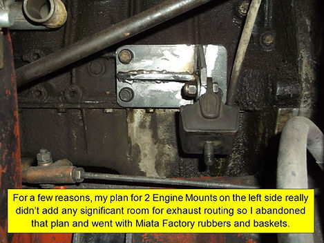
Engine Mounts:
With my 3-Engine-Mount plan dismissed we moved onto getting something closer to the stock Miata design..
Geometry
Of course the only way to really do this is to place the engine in situ and start making cardboard templates, one portion at a time. Drivetrain Geometry is crucial and we worked to get it as close to perfect as possible first.
The Miata had a fairly steep angle where the Engine Bracket meets the Frame Bracket, something like 60 degrees. Personally I think Mazda's steepness was so that the bolts that go into the engine work more in “sheer” rather than pulling on the threads to support the motor.
Some guys make them horizontal, but like Dan, we figured 45 degrees should work well. I thought it a good compromise in that as the rubber mounts settle they would exert less outward force on the frame than if the mounts were at 60 degrees.
By doing it that way we were able to have the engine side of the bracket go out to a point almost over the frame rail, pretty straight forward.
We removed the small bracket on the Starter Motor, which I believe is there to mitigate torque forces during Starter operation, and put that aside for now; later I will modify it or fabricate something similar..

Building ‘em
Then we just traced the footprints of the Engine portion of the factory Miata mounts for basic size and shape.
Drilled the holes appropriately and cut some cardboard to reflect our 45 degrees and planned to use the stock Miata rubber mounts. Cheap, effective, and on-hand.
By ball-parking where we wanted the rubber bits to be we started cutting and welding up some 1/4” steel to make it work. Again, 1/4” is definitely overkill, but it was sitting right there.
Although we considered the order in which to weld the bits, some parts were still difficult to get at with the Mig wand.
Used welding magnets where able, but at some points a simple block of wood to brace stuff in the perpendicular so we got perfect 90 degree bits.
Once the vertical parts were welded on we put up a test piece and drilled the required holes in it before welding it to the rest of the mount.
On the lower mounts, similarly with cardboard we test fit stuff and then cut it out of steel and welded it up. First the piece that holds the other part of the rubber mount and then worked down.
The biggest revelation I had at this point in the build was Removable Engine Mounts. When looking at other such swaps, I noticed that guys welded the brackets directly to the frame; because we didn't have a working example of our set-up I was concerned about doing it that way only to have to cut them off later for a better fitting solution; didn't want to weaken the Frame like that.

Removable Lower Engine Mounts
By drilling through the hollow box frame and welding Tubes into the Frame and grinding them off level at the top, we were able to drop bolts through to secure the lower part of the Engine Mount. This worked out great, especially as we later massaged the Engine Height and needed to add Shims in there. The Shims are a temporary fix, later I'll make new Engine Mounts the correct size, but they will still be bolt-ins with oblong holes for any later adjustments.
We made the bases of the mounts long enough that the Grade 8 bolts could slide in past the rest of the mount without any trouble. That also allowed fitment between other components on and with-in the frame.
For nuts, I was going to use Nylocks but the guys at “Bolts Plus” suggested what I think are called “Prevailing Torque Nuts”, basically an elongated nut that puts more friction on the male threads to prevent it from backing off. They seem to be working fine, but I don't know if you should ever re-use them after removal? As an added benefit, they are not as thick as Nylocks so my bolts did not have to extend down further than necessary.

Safety Consideration
As mentioned earlier, modern Engine Mounts seem to have a metal “Basket” around them that negate the need Triumph saw in putting the Retention Cable from the Engine back to the Frame. Naturally we kept those Baskets and had no need for a Cable.
When installing the “baskets” obviously we made sure that the drain holes in the two corners were at the bottom.

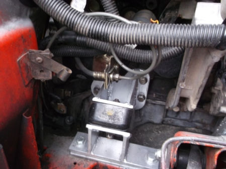
As mentioned earlier, the two shims we used for final adjustment are visible in the above images. I'll soon re-do those lower mounts to clean it up a bit.