Steve's Triumph Spitfire 1600
The ongoing saaaaaaga

General Fitment and Functional Concerns:
(These are "general" descriptions, with time I will add links with much more detail)
Naturally my brother and I looked at the big picture first and decided that some things lend themselves pretty well to relocation, and of course others do not.
Initially my intention was to get that Driveline as low as possible; clear that Bonnet and with a lower centre of gravity allow better handling. In the end, for this particular swap (Mazda 1.6) that was not the best plan. It was only later after carefully measuring stuff in situ that we realized Drive Train Geometry and surprisingly to us anyway, as we had not yet considered it, room for Exhaust routing between the Engine/Transmission and Frame Rails would be interesting with the Assembly that low.
In hindsight, right from the beginning targeting 1” or so below the Bonnet is the smartest way to go.
So here are the biggies!
-
Bonnet
-
Harmonic Balancer
-
Shifter Location
-
Firewall and Battery Box
-
Transmission Case
-
Clutch Slave
-
Engine/Tranny Angle Relative to the Differential
-
Prop Shaft Angle
-
Engine Mounts (including exhaust considerations)
-
Exhaust
-
Cooling
-
Air Intake, Airflow Meter, and Filter
-
Electrical
-
Fuel
Test fitting began...
Bonnet:
Really important to me to leave the Bonnet unmolested.
We managed to do the entire swap, many INs and OUTs, without removing the Bonnet. Because it was such an important part of the build I wanted to be able to check Bonnet closure with every change we made. It took only a few seconds longer and a little more care each time we pulled and replaced the Motor/Tranny, but it was worth it.
As we went along, much like Dan did with modelling clay, we used Dollar Store Playdoh in balls on top of the Engine, Battery, Clutch Master etc. we immediately knew if there would be any interference. I even crawled under where the Rad would've been with a light to have a look a few times.
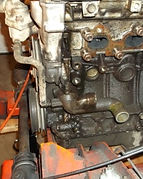
Harmonic Balancer and General Fitment:

It was clear that we would have to slightly relieve the Frame Cross-Member to make room for the forward part of the Oil Pan and tuck the Harmonic Balancer behind the Steering Rack just enough to allow a belt change.
Another option would entail finding (and they are getting harder to come by) an Underdriven Crank Pulley (Dan did this with success). Reading much about that option I decided against it. It is not a huge issue for a stock Miata Motor but if one thinks a Turbo may come later I think it would then have been a bad decision; it would be very difficult to modify at that point. Mazda did a great job with this Motor, seems sensible to keep as much of it as possible.
Some discussion has occurred wrt other Engine Swaps about modifying the Oil Pan to clear that Cross-Member. To start with, the Miata Oil Pan is shaped correctly already and has the Oil Strainer routed from the front to the lowest point at the back of the Pan so not much room will be gained. It is also aluminum, and although I suspect doable, not something we wanted to tackle. I would also not want to mess with the Oil Baffle mounted the entire length under the Crank.

Shifter Location:
Tied to the fore/aft placement of the Harmonic Balancer of course would be Shifter Location. In my mind the perfect location would be slightly aft of the stock location as I always felt it was slightly too far forward.
When I first saw the Miata 5-speed I immediately figured that moving the shifter 4” further forward on that Transmission would not be too difficult. As it turns out that's exactly what a number of guys have already done. The best description is probably here.
I also had another plan in my back pocket for another few inches but hoped we wouldn't need it. Unfortunately we did need to employ that plan and got the Shifter as far forward as I think possible but still had to massage the Hand Brake location. That was not heart-breaking as we also massaged the arch between the seats to help with Drivetrain clearances.

Firewall and Battery Box:
Firewall trimming was not physically difficult, but they were really the first cuts we made, so psychologically it sure was tough.
First the Shelf Area was cut away and down the right side.
Then making room for the Intake Manifold meant cutting into the Battery Box. I didn't want to mount the Battery in the Trunk; weight distribution is already great and I didn't want to occupy more Trunk space when a perfectly adequate spot already existed up front. I was lucky enough that my brother had thought ahead and brought with him an old Honda Accord Battery that is much narrower front-to-back than the one I was using. The Miata battery likely would have worked, but has less power and is unique to the Miata so I was happy with the more common Group 51R battery.
Using the narrower Battery also provided me the room to run all the Wiring just in front of the Battery but inside the Box and though a hole made on the outboard part of the Box. This was terrific for fitment of the Main Fuse Block within the Cabin on the right side of the Passenger Footwell as others have done. Some have chosen to put it in the Battery Box, but I prefer it inside the Cabin.


I have considered extending the Battery Box aft a bit to allow for a larger Battery, perhaps with Side Terminals which I much prefer, but after a full season with the car, that has become a very low priority.
Another consideration with the Firewall was how to seal the Tunnel Cover. The stock Spitfire Tunnel Cover is pretty simple, flat at the Firewall. I decided to try to make the Firewall with a lip to attach a modified Tunnel Cover, much like the original, but a little more shapely; unfortunately haven't tackled that yet. In all honesty I think I could have done a better job with that Firewall / Tunnel Cover Interface.... really important to have it be able to slide forward against something flat or even at a slight angle. That was my intent, but I think I may have messed up a surface or two.
An immediate thought was to do the new Tunnel Cover in multiple pieces... Not there yet, but will let you know.
Transmission case:
Looking at the Miata Transmission it is very obvious that the Cast-In Bracketry that holds the PPF (Power Plant Frame) would need to be cut/ground off. The casting on mine and I'm sure all of them, as I could see from the inside, did not have any channels or such that went into the bracket portion. Cutting this off was a pain my brother endured with the wrong tools, sorry Klaus; best to get aluminum cutting and grinding wheels.
In all of our fitment attempts we were pretty certain some minor trimming was needed on the inner Frame Rails. A tiny bit was shaved off the Seams at some points but after more manipulation of Engine Height and Angle to get the assembly to match the Differential Angle I'm not convinced we needed to trim it at all.
We also cut a notch out of the small Frame Cross Member at the aft of the Tranny... again, not sure that was required either.
It's rather easy to criticize us at this point....saying why would you cut so much? But seriously without another example of a swap done this way, there were many changing considerations. And, the trimming we did was for the most part pretty minimal.


Clutch Slave:

To use the Miata Clutch Slave Cylinder we had to relieve the right Frame Rail.
Seeing as the Miata Clutch is very light to begin with, a BETTER option, with less trimming required, would have been to shorten the Clutch Lever by an inch or so and adjust the geometry of the Slave Cylinder housing, or better yet where it attaches to the Bell Housing.
The BEST solution would have been a Hydraulic Throw-Out Bearing, fully contained inside the Bell Housing; I suspect this may have meant NO alterations to the frame at that location. I always come up with these great ideas after the fact!!!... Hopefully someone else can report back on these and any other options.

Engine/Tranny Angle Relative to the Differential:
Something that can be easily overlooked but most certainly should not, is Drivetrain Geometry.
After tonnes of reading on the subject I took this pretty seriously. The last thing I wanted after all this work was any vibration at speed.
My reading indicated that the Tranny Output Flange and Differential Input Flange should really be parallel on all planes, worst case within 1/2 degree. One option we kept in our back pockets was the possibility of slightly modifying the Forward Bushings of the Diff to better match the Tranny Output Shaft; fortunately with some wangling we nailed it just by adjusting the front end of the drivetrain.
We ended up raising the engine about an inch at the front, still leaving an inch or more between it and the Bonnet, and lowering the Transmission a touch.
Another thing that I looked carefully at was the engine angle relative to the horizon. My estimation is that Mazda had it at about 1.5 degrees aft tilt. We ended up right in there too. I believe that this is important for proper lubrication of the Transmission.

Prop Shaft Angle:
Next, Prop Shaft angle should be considered. Because of the level (height off the ground) difference between Transmission Output Flange and Differential Input Flange and the short distance between them, this can be a challenge.
Ideally the angle of the Propshaft would be near 1.5 degrees off perpendicular to the Flanges, more is okay to a point, but you definitely don't want it right in line. The Miata appears to have about 4 degrees, and mine ended up at about 6 degrees; although slightly concerned... we didn't have much choice. In the end we were pleased to experience no vibration at all at any speeds.
Naturally the Prop Shaft needed to be cut and balanced with the Aft Flange of a Spitfire Shaft grafted on. If we had an extra one on hand we may have attempted it ourselves, but it was only 200 bucks labour so we had the pros do it. I'm proud to say that's all we had to pay to have done.
Staked U-Joints on the Miata Shaft make it more difficult to replace them; Mazda says to replace the entire Shaft, but enough guys have written about fitting new U-Joints that I wouldn't hesitate doing it myself. Mine seemed good and the Drive Shaft Shop guys said that the U-Joint on there was fine so we left it.
Exhaust:
After getting a decent Drivetrain fit and ensuring the Bonnet would remain unadultered we looked at Exhaust being the next priority.
Some guys root their Exhaust outboard of the Frame Rail at the Engine and not sure what they do with it after that? (I think often they use sidepipes). Seems to me that that routing would require it to then pass under the Frame and significantly reducing ground clearance, not to mention potentially, turn radius. Our priority was to get it inside the Frame Rail and along the Tranny to the normal routing.
This required some manipulation of the Header… well… complete reconstruction really. In the end our Collector Pipes are not all the same length, not that they were from the factory anyway, but we weren't too concerned about the 1 or 2 HP loss and tuning seems to be fine.
We got it routed forward of the Engine Mount and tucked up pretty nicely along the Transmission. We also added a small (no real-estate for larger) Flex Pipe and of course a Flange connecting to the aft part of the Exhaust which you may have already read was now 2” all the way back.


Boy that high heat black paint looked great for a few days! Until we mounted the exhaust and ran the car that is! Not only did it just burn off on our first test drive, but it nearly asphyxiated us with thick smoke billowing through the open tunnel. Too funny.
Engine Mounts:
I originally had a cool plan to use three Engine Mounts, the Miata one on the right side and two Spitfire Mounts on the left, one in the normal position on the Turret and another with a Modified Bracket at the back. The intention was to leave room for the Exhaust to route forward of that Bracket but still inboard of the Frame Rail. In the end the Aft Mount took up almost as much room as the Miata Factory Mount so that decision was easy, we just went with the Miata Mount locations on both sides.
Because we didn't have a working example of our set-up I was concerned about welding Engine Mounts to the Frame only to have to cut them off later for a better fitting solution; didn't want to weaken the Frame like that. My solution was to weld Tubes into the Frame through which bolts could secure the lower part of the Engine Mount. This worked out great, especially as we later massaged the Engine Height and needed to add Shims in there. The Shims are a temporary fix, later I'll make new Engine Mounts the correct size, but they will still be bolt-ins with oblong holes for any later adjustments.


The Miata had a fairly steep angle where the Engine Bracket meets the Frame Bracket, something like 60 degrees. Some guys make them horizontal, but like Dan, we figured 45 degrees should work well.
As a side note it seems modern Engine Mounts have a metal “Basket” around them that negate the need Triumph saw in putting the Retention Cable from the Engine back to the Frame. Naturally we kept those Baskets and had no need for a Cable.
Cooling:
Snowballing being what it is, with our Exhaust routing, the Coolant Mixing Chamber would then be right in the way of the Exhaust. I saw that ahead of time and had a few ideas.
Dan had a clever solution to cut and weld the main pipe onto the other side for better geometry. My aluminum welding, having never attempted it, would not be up to the task and in the end I actually prefer our solution. We rotated the Mixing Chamber 180 degrees so that it would face forward. This made routing to the Rad easier, but required some manipulation of the Return Pipe coming from the back of the Block. I fabricated some bracketry to accommodate those changes and they have held out nicely.
Choice of Radiator was a very minor concern, there are many shapes and sizes available and I think even a custom Rad wouldn't be that expensive. In the end we managed to get the Miata one to fit, even with the Hydraulic Bonnet Lifts I installed a few years ago.
One consideration was getting the Cooling System full of coolant; the Rad Filler Neck was now slightly lower than the top Rad Hose. The guys at Nitro Industrial Sales at 8520 Jane St. Concord ON were great and helped me assemble some bits to cut and weld together to have a Remote Filler Neck at the top of the top hose.

Air Intake, Airflow Meter, and Air Filter:
There was some uncertainty just how this would pan out. I didn't want to run the Air Filter Assembly back over the very hot Exhaust Header like others have done, so I found room for it just behind the Rad Fan with the Filter in fresher, cooler air outboard of that.
One concern was keeping the Air Flow through the Intake Pipes smooth so I didn't want to mount the unit too high requiring more bends in flow as well as more fabrication / manipulation of Pipes. I also read that keeping the Resonance or Dynamic Chamber is a good idea, so we did. I did some fidgeting around with the Airflow Meter and because it is spring-loaded and didn’t depend on gravity it seemed that it wouldn't complain too much about being mounted diagonally. It didn't mind at all; works like a charm and fits in there beautifully.
Of course the notion of routing some Intake Tubing out in front of the rad was forefront in my mind, but with the Inner Fender Liner that comes down with the Bonnet and Hydraulic Bonnet Lifts it would mean routing under the Rad, being quite conspicuous and again reducing road clearance. Shame though, that would've been nice.

Electrical:
Can be daunting, but you just eat it one bite at a time.
On the dining room table, I laid out the entire Electrical Harness of the Miata. By reviewing detailed Wiring Diagrams I learned how it all worked together and determined what I would need to fire the Fuel Injection, Ignition, ECU etc etc. and drew up my own revised hybrid diagram. After that it was pretty straight forward.
The first time we attepted to start the car, it fired up on the initial try and everything worked, even the Back-Up Lights. Time in recce is seldom wasted! :)


Fuel System:
No offence to guys who mount Carbs to an Engine that originally had Fuel Injection, but really?
That's one of the beauties of this swap and it was so incredibly easy.
Anyway, it all worked out really well. Just mounted an External Fuel Pump of appropriate pressure below the Fuel Tank, added the Miata High Pressure Filter and re-bent those lines to fit into the Spit. Just wanted to be really careful to use good high pressure hoses. I'm not fond of all those fuel connections in the Boot but for now it will have to do.
We did muck about cutting up an old Spitfire Fuel Tank to see about mounting the Miata Fuel Pump in there, but it turned out to be impractical at this point. The Baffles in the Tank and service issues if it needed to be pulled out had us take the easy route for now.

Soooooo...
Those are the biggies. I will provide links from these individual topics to more details and images.